Looking for some help with wiring. My ‘79 J10 had a 360/T18 that was pulled out a few years back. I put a 2004 5.3/4L60e back in, plus the rebuilt D20 and a Wagoneer auto column. The wiring sat disconnected for a few years due to life and now I’m trying to get it running. I have a reworked LS harness which is connected to the eng/trans but nothing else, and I’m also putting in a Dakota Digital dash.
Open questions-
- I have ~10ga red and yellow wires disconnected at the dash and firewall, and they thread thru the column and fuse panel and maybe the ignition switch? What are these?
- there is also a ~10ga red/white trace wire I see imbedded in the harness in the dash and disconnected on the firewall side, also possibly thru the ignition switch? Looks like it’s the old electronic ignition setup as it pairs with a light blue wire into a two pin connector. Is this any use to me for my swap?
- what is the main power source for the fuse panel so I can connect it… where?
- I need to find or set up:
- the wire that provides power to the fuse panel
- constant power on
- ignition power on
- the wire that should go to the solenoid/starter
**just to be clear - ALL original wires are disconnected. There is no battery, no battery cables, all that came out with the original engine. All the wires that came thru the firewall Sadie of the fuse panel are there but disconnected. I can put in a battery and the cables, just have no clue which J10 wires to use for the items listed up above. I do have the Tech Manual and all the OLJeep diagrams, but none are clear on the above.
These answers would be a great start! Any help would be appreciated. I’ve done this before along with complete new wiring and an LS swap in my ‘51 Chevy truck but this one is just not computing yet. Thanks!
Scott
‘79 J10 LS Swap wiring Help
-
Scott2
Topic author - Posts: 11
- Joined: Sat Sep 22, 2018 8:15 am
- Location: Colorado front range
-
 tgreese
- Posts: 7197
- Joined: Fri Jun 08, 2012 6:31 am
- Location: Medford MA USA
Re: ‘79 J10 LS Swap wiring Help
Ok, have you examined the factory wiring diagram on the Tom Collins site? Do you own the '79 TSM?
https://oljeep.com/ - free to read and download. The diagram is there both in the electrical section and as the '79 TSM. You can also buy the manual for your own on media or paper.
The 10 ga wires should be the charging wire that originally went to the ammeter in the dash. The red alternator charge current wire goes from the alternator, to the bulkhead connector in the firewall. Under the dash it branches to feed the ignition and lights. Then to the ammeter, where it goes through and changes to yellow. Back to the bulkhead connector and to the battery via the starter solenoid.
These Jeeps came with electronic ignition from the factory, and there would be a feed wire to the ignition module and coil from the ignition switch. The ignition also used a blue wire that both bypassed the coil resistance wire (ballast resistor) and signaled the ignition module to retard the spark. This provided hotter and easier starting, respectively.
The connections to the dash all went thought the bulkhead connector on the firewall. Do you have the engine side of the connector? Using the existing wiring would be way way easier if you had the mating half of the bulkhead connector.
Suggest you read and understand the wiring diagram and match to what wiring you have. Lots of material to help you there, in both the diagram and the table that names each circuit and locates it on the diagram.
You do not have the required permissions to view the files attached to this post.
Tim Reese
Maine beekeeper's truck: '77 J10 LWB, 258/T15/D20/3.54 bone stock, low options (delete radio), PS/PDB, hubcaps.
Browless and proud: '82 J20 360/T18/NP208/3.73, Destination A/Ts, 7600 GVWR
Copper Polly: '75 CJ-6, 304/T15, PS, BFG KM2s, soft top
GTI without the badges: '95 VW Golf Sport 2000cc 2D
Dual Everything: '15 Chryco Jeep Cherokee KL Trailhawk, ECO Green
Blockchain the vote.
-
Scott2
Topic author - Posts: 11
- Joined: Sat Sep 22, 2018 8:15 am
- Location: Colorado front range
Re: ‘79 J10 LS Swap wiring Help
Tim,
Yes, I have the OL wiring diagrams and the Tech Service Manual. I have studied all carefully - your comments are helping a lot.
First - I didn’t previously understand the ammeter and red/yellow connection. Pulled out the old dash and realized where my red & yellow connected. With the new digital dash the ammeter is gone so I can likely just connect these wires together now?
Second - both the 10ga red and yellow are intact from the firewall forward. The red still has the ring on the end so I could connect this to either the ls alternator or the red plastic GM connector box that mounts to the alternator mount and has a short alternator wire connector - correct? (The benefit is this allow me to easily run a power line to the LS relays for fuel pump, fan, etc.). The yellow wire also has the ring on the end plus the brown and short red wires with the two prong connector that appears to plug into a stock Jeep alternator. That should no longer be needed - correct?
Third - there is a 10ga red/white trace and blue wire that comes out of the firewall and goes to a two prong connector for the electronic ignition. Before the connector these wires branch off to a red and blue to a double rubber connector that goes to the starter solenoid. Would either of these be used as the starter signal for the ls starter?
Make sense?
Scott
-
tgreese
- Posts: 7197
- Joined: Fri Jun 08, 2012 6:31 am
- Location: Medford MA USA
Re: ‘79 J10 LS Swap wiring Help
1 & 2) You can connect them, but there is no reason to loop up to the dash if there's no ammeter. I have a voltmeter in my J20 now, and the red/yellow wires are connected like this. Before above, after below.
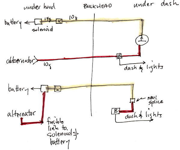
You need to connect the alternator to the battery, and the battery to the dash/lights. The above shows one way to do it; there are others, but this made the most sense to me. Can't advise you abut the LS parts - no experience with that. Regarding the other wire, 3) I would reconcile them with the original diagram first, then decide how to use them. The original ignition module has two connectors, one with two pins (red/trace 10 ga, light blue) and one with 4 pins. Red/trace looks like module power. Should be clear if you refer to the TSM diagram.
You need to connect the alternator to the battery, and the battery to the dash/lights. The above shows one way to do it; there are others, but this made the most sense to me. Can't advise you abut the LS parts - no experience with that. Regarding the other wire, 3) I would reconcile them with the original diagram first, then decide how to use them. The original ignition module has two connectors, one with two pins (red/trace 10 ga, light blue) and one with 4 pins. Red/trace looks like module power. Should be clear if you refer to the TSM diagram.
Tim Reese
Maine beekeeper's truck: '77 J10 LWB, 258/T15/D20/3.54 bone stock, low options (delete radio), PS/PDB, hubcaps.
Browless and proud: '82 J20 360/T18/NP208/3.73, Destination A/Ts, 7600 GVWR
Copper Polly: '75 CJ-6, 304/T15, PS, BFG KM2s, soft top
GTI without the badges: '95 VW Golf Sport 2000cc 2D
Dual Everything: '15 Chryco Jeep Cherokee KL Trailhawk, ECO Green
Blockchain the vote.
Maine beekeeper's truck: '77 J10 LWB, 258/T15/D20/3.54 bone stock, low options (delete radio), PS/PDB, hubcaps.
Browless and proud: '82 J20 360/T18/NP208/3.73, Destination A/Ts, 7600 GVWR
Copper Polly: '75 CJ-6, 304/T15, PS, BFG KM2s, soft top
GTI without the badges: '95 VW Golf Sport 2000cc 2D
Dual Everything: '15 Chryco Jeep Cherokee KL Trailhawk, ECO Green
Blockchain the vote.
-
Scott2
Topic author - Posts: 11
- Joined: Sat Sep 22, 2018 8:15 am
- Location: Colorado front range
Re: ‘79 J10 LS Swap wiring Help
Tim,
I spent some more time looking at the diagrams and thinking this thru.
First - If I connect the 10 ga red and yellow in the dash I get the following: once connected properly it will supply power to all the connections that each wire has such as to the fuse panel, the light and ignition switches; a heavy gauge line I can run between the alternator and the solenoid stud where the positive battery cable will also connect; connect the alternator via the LS GM red plastic junction box (which has a connection stud and can also feed my LS relays (fan, elec fuel pump, and PCM) from that; and then have a known constant power-on source under the dash. Are there any downsides you are aware of?
I will have to actually replace all the wire outside the firewall with something like 4ga since the newer alternator puts out over double the old J10 unit. I will get a junction box to set on the firewall side of the fusebox and connect everything (old red, old yellow, new 4ga) up there. I'll also add a big, fat fuse to the alternator line at least.
Second - for the starter excite wire, I ran through all the diagrams and determined that the light blue wire is that wire. I will most likely get a new Neutral Safety Switch and run the blue wire thru that and over to the solenoid. Then it's testing time. Once everything is working, I can get a continuity tester and poke around and find an ignition-on wire for my Dakota Digital modules.
Does all this sound right? Any major oversights? Thanks so much for going through it with me and getting me straight. It was really helpful!